EKU5-T1+T2-12-SPD
EKU5-T1+T2-12-SPD
EKU5-T1+T2-12-SPD
EKU5-T1+T2-12-SPD
EKU5-T1+T2-12-SPD
EKU5-T1+T2-12-SPD
EKU5-T1+T2-12-SPD
EKU5-T1+T2-12-SPD
EKU5-T1+T2-12-SPD

AC SPD Type 1+2, Iimp 12.5kA, Class I+II Surge Protective Device

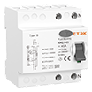
The EKU5-T1+T2-12 is a series of Class I+II Iimp 12.5kA AC Surge Protective Devices designed to protect against indirect and low-intensity direct lightning strikes. These SPDs are equipped with high-energy Metal Oxide Varistors, ensuring low response time and characteristics suitable for both Class I and II protection.

● Standard: IEC/EN 61643-11
● Surge Rating: Iimp=up to 12.5 kA (10/350 µs), In=up to 30kA (8/20 µs)
● IEC/EN Category: Class I+II / Type 1+2
● Max. continuous operating voltage: from 150V up to 385V AC
● Housing: Pluggable Design

Inquire NOW PDF

AC SPD Type 1+2, Iimp 12.5kA, Class I+II Surge Protective Device

Inquire NOW PDF

Porduct Overview

The EKU5-T1+T2-12 is a series of Class I+II Iimp 12.5kA AC Surge Protective Devices designed to protect against indirect and low-intensity direct lightning strikes. These SPDs are equipped with high-energy Metal Oxide Varistors, ensuring low response time and characteristics suitable for both Class I and II protection. The modular design with plug-in inserts allows for easy and quick replacement of function modules in case the MOV reaches the end of its lifespan due to high intensity or frequent overvoltage peaks.

Technical parameters

Technical Data

Table 1
No.of poles 1P 2P 3P 4P 1P+NPE 3P+NPE
Network systems TN-S,TN-C,TT(only L-N) TN-S TN-C TN-S TT,TN-S
Mode of protection L-PE,N-PE(onlyTN-S), L-PEN,L-N L-PE,N-PE L-PEN L-PE,N-PE L-N,N-PE
Protective elements High Energy MOV High Energy MOV and GDT

Table 2
Max. continuous operating a.c.voltage Uc(L-N) 150V 275V 320V 385V
Uc(N-PE) 255V
Impulse discharge current (10/350μs) limp 12.5kA
Norminal discharge current (8/20μs) In 30kA
Maximum discharge current (8/20μs) Imax 60kA
Voltage protection level (L-N)/(N-PE) Up 1.2kV/1.5kV 1.5kV/1.5kV 1.6kV/1.5kV 1.8kV/1.5kV
Voltage protection level 5kA ≤0.6kV ≤1.0kV ≤1.2kV ≤1.3kV
Response time (L-N)/(N-PE) tA ≤25ns/≤100ns
Operating temperature range Tu -40℃ to +80℃
Max. backup fuse   160A gL/gG
Operating State/Fault Indication   Green/Red(L-N),Yellow(N-PE)
Cross-section area (Min.)/(Max.)   4mm²/35mm²
For mounting on   35mm Din rail
Enclosed material   Thermal Plastic UL94-V0
Degree of Protection   IP20 (built-in)

Dimensions

Basic circuit diagram


Installation Size

Product selection form

No. of Poles Max. Continuous Operating AC Voltage
150V 275V 320V 385V
1P EKU5-T1+T2-12-1P150 EKU5-T1+T2-12-1P275 EKU5-T1+T2-12-1P320 EKU5-T1+T2-12-1P385
2P EKU5-T1+T2-12-2P150 EKU5-T1+T2-12-2P275 EKU5-T1+T2-12-2P320 EKU5-T1+T2-12-2P385
3P EKU5-T1+T2-12-3P150 EKU5-T1+T2-12-3P275 EKU5-T1+T2-12-3P320 EKU5-T1+T2-12-3P385
4P EKU5-T1+T2-12-4P150 EKU5-T1+T2-12-4P275 EKU5-T1+T2-12-4P320 EKU5-T1+T2-12-4P385
1P+NPE EKU5-T1+T2-12-1PN150 EKU5-T1+T2-12-1PN275 EKU5-T1+T2-12-1PN320 EKU5-T1+T2-12-1PN385
3P+NPE EKU5-T1+T2-12-3PN150 EKU5-T1+T2-12-3PN275 EKU5-T1+T2-12-3PN320 EKU5-T1+T2-12-3PN385
With Remote Signaling
1P EKU5-T1+T2-12-1P150S EKU5-T1+T2-12-1P275S EKU5-T1+T2-12-1P320S EKU5-T1+T2-12-1P385S
2P EKU5-T1+T2-12-2P150S EKU5-T1+T2-12-2P275S EKU5-T1+T2-12-2P320S EKU5-T1+T2-12-2P385S
3P EKU5-T1+T2-12-3P150S EKU5-T1+T2-12-3P275S EKU5-T1+T2-12-3P320S EKU5-T1+T2-12-3P385S
4P EKU5-T1+T2-12-4P150S EKU5-T1+T2-12-4P275S EKU5-T1+T2-12-4P320S EKU5-T1+T2-12-4P385S
1P+NPE EKU5-T1+T2-12-1PN150S EKU5-T1+T2-12-1PN275S EKU5-T1+T2-12-1PN320S EKU5-T1+T2-12-1PN385S
3P+NPE EKU5-T1+T2-12-3PN150S EKU5-T1+T2-12-3PN275S EKU5-T1+T2-12-3PN320S EKU5-T1+T2-12-3PN385S

Download Files

Porduct Overview

The EKU5-T1+T2-12 is a series of Class I+II Iimp 12.5kA AC Surge Protective Devices designed to protect against indirect and low-intensity direct lightning strikes. These SPDs are equipped with high-energy Metal Oxide Varistors, ensuring low response time and characteristics suitable for both Class I and II protection. The modular design with plug-in inserts allows for easy and quick replacement of function modules in case the MOV reaches the end of its lifespan due to high intensity or frequent overvoltage peaks.
Technical parameters

Download Files

Get in Touch

Captcha Code
×
We value your privacy
We use cookies to provide you with a better online experience, analyse and measure website usage, and assist in our marketing efforts.
Accept All