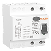
EKCS101-MCB-Changeover

Din Rail MCB Changeover Switch

● Standard: IEC60947-3
● Compact design
● Rated Current: 16-40A
● Front operation with three stable positions I-0-II
● Off at middle position
● Can be mounted with other products viz MCB, RCCB, Isolator in distribution board
● Easy snap on DIN rail mounting
● Certificates: CE, CB

Inquire NOW PDF

Din Rail MCB Changeover Switch

Inquire NOW PDF

Porduct Overview

Changeover switch is designed to transfer a house or business electricity from the commercial power grid to a local generator when an outage occurs also known as transfer switches, they connect directly to the generator commercial power supply or line and the house.

EKCS101 rail-mounted dual power conversion isolation switch has four functions of on, off, conversion and isolation. It can be freely switched on and off between two loads carried by a group of lines, or on two power sources. It is used for on-off and switching between, using DIN standard rail (35×7.5) installation, the shell is made of PA66 injection molding, with high flame-retardant performance, it is an ideal product that needs to be used for switching and opening and closing in industrial equipment and circuits. The maximum current can reach 40A, and it is convenient and safe to install and wire on the guide rail.

1.When the handle hits the I position: 1.5 and 2.6 are connected.
2.When the handle hits the position of II: 1.5 and 4.8 are connected.
3.When the handle is in the middle position: both groups are disconnected.

Technical parameters

Technical Data

Rated Voltage 240/415V~
Rated Current 16,25,32,40A
Rated Frequency 50/60Hz
Number of Poles 1,2,3,4P
Utilisation category AC 22A
Contact form I-0-II
Electrical Life 1500 Cycles
Mechanical Life 8500 Cycles
Protection Degree IP20
Ambient Temperature -5℃...40℃
Terminal/ Cable Size 16mm²
Mounting On Din EN60715(35mm) by means of fast clip device

Dimensions

Wiring diagram


Overall Dimension


Product selection form

Poles Reference No. Specification
1P EKCS101-1-16 Modular Changeover Switch 1-0-2 1P 16A
EKCS101-1-25 Modular Changeover Switch 1-0-2 1P 25A
EKCS101-1-32 Modular Changeover Switch 1-0-2 1P 32A
EKCS101-1-40 Modular Changeover Switch 1-0-2 1P 40A
2P EKCS101-2-16 Modular Changeover Switch 1-0-2 2P 16A
EKCS101-2-25 Modular Changeover Switch 1-0-2 2P 25A
EKCS101-2-32 Modular Changeover Switch 1-0-2 2P 32A
EKCS101-2-40 Modular Changeover Switch 1-0-2 2P 40A
3P EKCS101-3-16 Modular Changeover Switch 1-0-2 3P 16A
EKCS101-3-25 Modular Changeover Switch 1-0-2 3P 25A
EKCS101-3-32 Modular Changeover Switch 1-0-2 3P 32A
EKCS101-3-40 Modular Changeover Switch 1-0-2 3P 40A
4P EKCS101-4-16 Modular Changeover Switch 1-0-2 4P 16A
EKCS101-4-25 Modular Changeover Switch 1-0-2 4P 25A
EKCS101-4-32 Modular Changeover Switch 1-0-2 4P 32A
EKCS101-4-40 Modular Changeover Switch 1-0-2 4P 40A


Download Files

Porduct Overview

Changeover switch is designed to transfer a house or business electricity from the commercial power grid to a local generator when an outage occurs also known as transfer switches, they connect directly to the generator commercial power supply or line and the house.

EKCS101 rail-mounted dual power conversion isolation switch has four functions of on, off, conversion and isolation. It can be freely switched on and off between two loads carried by a group of lines, or on two power sources. It is used for on-off and switching between, using DIN standard rail (35×7.5) installation, the shell is made of PA66 injection molding, with high flame-retardant performance, it is an ideal product that needs to be used for switching and opening and closing in industrial equipment and circuits. The maximum current can reach 40A, and it is convenient and safe to install and wire on the guide rail.

1.When the handle hits the I position: 1.5 and 2.6 are connected.
2.When the handle hits the position of II: 1.5 and 4.8 are connected.
3.When the handle is in the middle position: both groups are disconnected.

Technical parameters

Download Files

Get in Touch

Captcha Code
×
We value your privacy
We use cookies to provide you with a better online experience, analyse and measure website usage, and assist in our marketing efforts.
Accept All